高分,英文翻译,急急急!!! 不要在线翻译,要人工翻译,谢谢
The front end circuit of the new comparator is shown in Fig. 1. The configuration is derived from a Gilbert-type cell [4] with the addition of a conventional long-tailed pair current drive circuit and gain peaking. The input transistors QI and Q2 operate at low collector currents, about 0.5 mA, to ensure a low input bias current without input emitter followers, while the cascode devices Q5 and Q6 reduce Miller effect input capacitance terms. The cross-coupled pair Q3 and Q4 raise the small signal gain to 8.4, while maintaining a 3 dB rolloff frequency over 400 MHz, assisted by the peaking effect of the pole-zero cancellation resistors R3 and R4 [5]. The input configuration has some similarity to that of [6], but by the use of a faster process, and pole-zero cancellation, an improvement factor of 10 has been achieved. This is not without cost, primarily in power, and to some extent in power-delay product. However, in the case of a single comparator this is not usually significant; the criterion applied is absolute speed. An approximate indication of the gain distribution (based on SPICE prediction) is shown in Fig. 2. The stage gain-bandwidth tradeoff was considered very carefully in relation to the rest of the circuit and with respect to the input dynamic range requirement and output configuration. The final choice of gain distribution was arranged for similar rolloff points in each stage, although the limiting factor is the interstage level shift, which introduces both an attenuation and a reduction in bandwidth. Level shifting and the ECL-compatible output stages were essential in this application, but do represent the main speed limitation of the present design; a more desirable configuration would use direct termination of a multiple Gilbert cell array.
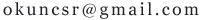
The comparator was designed on a 3 um minimum feature size junction isolated bipolar process, a variant of a current 4 Mm production process. A cross section of an n-p-n transistor is shown in Fig. 4. Small geometry devices offer low capacitances with good fT's (greater than 5 GHz) at reasonable current densities. Base width on the process is 0.15 um and emitter depth 0.3 um. Junction isolation offers process simplicity but suffers from higher sidewall capacitance. Circuit variants on an oxide isolated process are under investigation.
手工翻译,本人有电子背景 ; )
——————————————
图1给出了新的比较器的前端电路。其基本结构是一个吉尔伯特电路单元,再加上常用的电流驱动电路和增益峰化。输入三极管Q1和Q2集电极工作电流较低,约0.5mA,以保证没有射极跟随器情形下的低输入偏置电流;而共源共栅放大器Q5和Q6能降低输入电容带来的米勒效应。交叉耦合对Q3和Q4将小信号增益提升到8.4,同时在零极点相消的电阻R3、R4的增益峰化作用协助下,保持400MHz以上的3dB截止频率。输入部分的结构跟【6】中的类似,但通过采用更快的方式以及零极点相消模块,实现了10倍的增益。但这在功率上是有代价的,对一些功率延时(power-delay)的产品存在影响。然而在单一的比较器上通常这并无大碍;我们看重的指标是绝对速度。图2给出了近似的增益分布(由Spice仿真而得)。在确定增益-带宽平衡时,充分考虑了电路其他部分的结构、输入动态范围和输出结构。在确定增益分布时尽量使各级的截止频率接近,尽管其主要限制因素是级内的电平位移(造成增益降低和带宽变窄)。电平移动和兼容射极耦合逻辑(ECL)的输出级在本例中是不可或缺的,但确实也构成了本设计中最主要的速度限制因素;直接采用多吉尔伯特单元阵列作为端电路更能满足速度需求。该比较器采用最小尺寸为3um的结隔离双极性晶体管生产工艺,为一种当前的4um生产流程的变种。图4给出了一个NPN晶体管的横截面。小尺寸的元件在合理的电流密度下可提供较好的FT(大于5GHz)而电容较小。该工艺中的基底宽度为0.15um,发射区深度为0.3um。结隔离结构使得工艺流程简化,但带来较高的边墙电容。氧化隔离工艺下的电路变种(变式)正在研究之中。
——————————————
个别专业词汇不常见,还望自行校正一下。
祝好!
在比较器的设计了一种三恩最小特徵尺寸交界处的过程,是一个孤立的双相性精神障碍4毫米的变种生产过程电流。一个n-p-n断面晶体管是显示在图4。提供低只小几何装置具有良好的《金融时报》的(大于5千兆赫)以合理的电流密度。基础宽度等因素对过程为0.15澳大与发射极深度0.3微米,提供简单但交界处隔离过程遭受更高的边墙电容。电路变体一个氧化孤立的过程都是在调查中。